Design for Manufacturing (DFM) is the bridge between a pristine CAD model and the physical part sitting on the welding table.
For CAD enthusiasts, DFM is about math and geometry. For seasoned fabricators, it’s about avoiding headaches, wasted scrap, and hours of grinding.
Today, we are stripping away the complexity and diving deep into the nuances of Sheet Metal Design. moving beyond basic flanges and into the techniques that make parts self-fixturing, dimensionally accurate, and safer to handle.
Part 1: the Bend
The most common error in sheet metal design isn’t the shape; it’s the unfolding. Metal doesn’t fold like paper; it stretches. If your CAD data doesn’t account for the physical deformation of the material, your bolt holes simply won’t line up.
1. Respect the Bend Deduction (BD)
When you bend sheet metal, the neutral axis shifts, and the material elongates. To get the flat pattern right, you must subtract that elongation from the total length.
- The Formula: Total Flat Length = Flange A + Flange B – Bend Deduction
- The Trap: Do not rely on your software’s default K-factor (usually 0.5) unless you have verified it.
- The Fix: Ask your shop for their Bend Table. The BD changes based on the V-die width, the tooling radius, and the material type. A generic K-factor is a guess; a shop-specific Bend Deduction is a guarantee.
- Calculator: Here is a good Bend Deduction Calculator
2. The “Oval Hole” Syndrome (Distortion Zones)
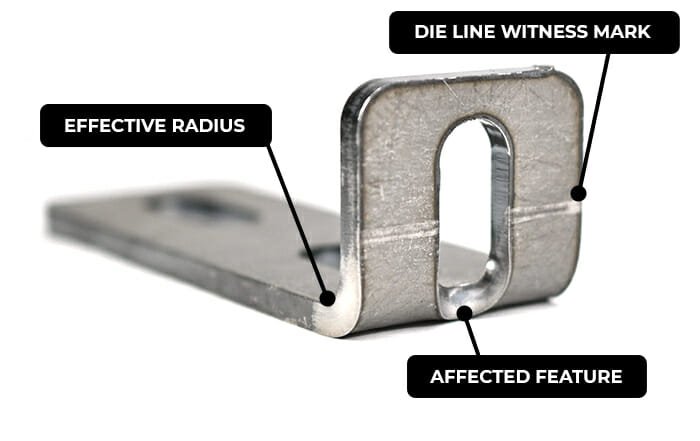
A common rookie mistake is placing a hole too close to a bend. As the metal stretches during forming, any hole located within the bend radius will deform into an oval or, worse, crack the edge of the part.
- The Rule: Keep holes away from the start of the bend radius by a distance of at least 2.5x Material Thickness.
- The Workaround: If you absolutely need a hole closer to the bend, you must cut a relief slot (a thin cutout) along the bend line in front of the hole to isolate it from the stretching forces.
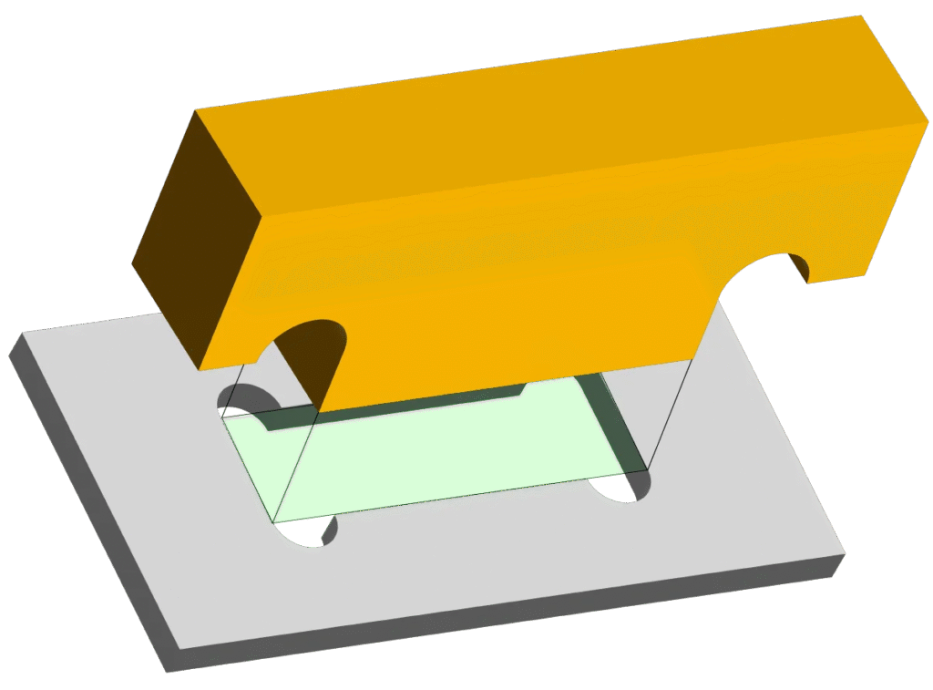
3. Minimum Flange Length
Press brakes work by forcing metal into a V-shaped die. If your flange is too short, it will slip inside the V-die rather than spanning across it, resulting in a mangled edge and an inaccurate bend angle.
- The Rule: Your flange length must generally be at least 4x Material Thickness (or roughly half the width of the V-die being used), try asking the bend operator what is the recommended minimum flange for each thickness.
- The Fix: If you need a tiny flange, design it longer and machine it down later (expensive), or add a “sacrificial tab” to bridge the die that can be snapped off later.
Part 2: Material & Safety
1. Material Behavior
- Mild Steel: Forgiving and consistent.
- Aluminum (5052 vs. 6061):
- 5052: Excellent for bending.
- 6061-T6: Hard and brittle. It is prone to cracking if the bend radius is too tight. Keep your internal radius >1x Material Thickness (ideally 2x) to prevent cracking.
- Stainless Steel: Beware of springback. Stainless has a memory; you often have to overbend it to get it to settle at 90°, which complicates angle precision.
2. Safety Fillets & Edge Rounds
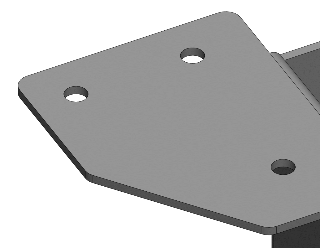
Laser-cut edges are notoriously sharp. While internal features usually get tumbled, external corners are razor blades waiting for a hand.
- The 1/16″ Rule: Unless your design requires a sharp corner for indexing, apply a small fillet (typically 0.060″ to 0.125″) to every external corner.
- Why it matters:
- Injury Prevention: Drastically reduces cuts during handling.
- Finish Quality: Paint and powder coat pull away from sharp corners, leaving a thin spot where rust starts. A radius ensures even coverage.
Part 3: Geometry & Reliefs
1. Bend Reliefs (The Anti-Tear Feature)
When you bend a tab that is part of a larger sheet (where the bend doesn’t go across the entire width of the part), the metal at the corners of the tab will tear.
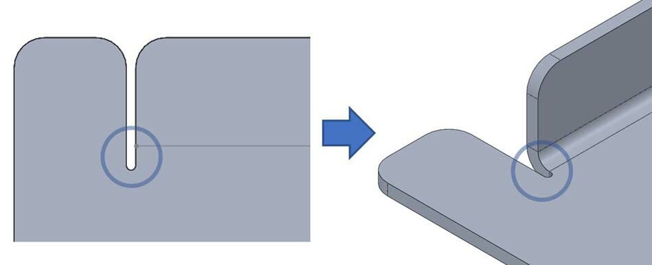
- The Fix: Add Bend Reliefs—small rectangular or circular cutouts at the base of the tab.
- Size: The relief should be as wide as the material thickness and extend past the bend line by roughly 0.030″. This physically separates the bending metal from the stationary metal.
2. Self-Fixturing Design (Tabs & Slots)
Eliminate the tape measure. Use tabs and slots to make parts “click” together before welding.
- The “Dog Bone” Relief: You cannot cut a perfect square corner with a laser; there is always a tiny beam radius. If you put a square tab into a square slot, it will bind.
- The Solution: Add circular reliefs (dog bones) to the corners of your slots. This ensures the tab seats fully flush and provides a predictable gap for weld penetration.
- Tolerance: Oversize slots by 0.005″ – 0.010″ to account for laser kerf and material variance.
Summary: The “Fabricator Friendly” Checklist
Before you hit “Export DXF,” run through this mental checklist:
- Bend Check: Did I use the correct Bend Deduction for the shop’s tooling?
- Distortion Check: Are my holes far enough away (2.5x thickness) from the bend lines?
- Die Check: Are my flanges long enough to span the V-die?
- Corner Check: Did I add fillets (min 0.060″) to external corners to protect the handlers?
- Relief Check: Did I add bend reliefs to tabs and “dog bones” to slots?
Design with the shop floor in mind, and your parts won’t just look good in CAD—they’ll slide into the press brake and come out perfect every time.